A good PCB layout for the ZVP1320FTA involves keeping the input and output capacitors close to the device, using a solid ground plane, and minimizing the length of the input and output traces. A 4-layer PCB with a dedicated power plane and a solid ground plane is recommended.
To ensure stability, ensure that the output capacitor has a low ESR, the input capacitor is properly sized, and the feedback resistors are chosen to provide a stable gain. Additionally, ensure that the device is operated within its recommended operating conditions and that the PCB layout is optimized for stability.
The maximum ambient temperature range for the ZVP1320FTA is -40°C to +125°C. However, the device's performance may degrade at higher temperatures, and the maximum junction temperature should not exceed 150°C.
Yes, the ZVP1320FTA is suitable for high-reliability applications. It is manufactured using a robust process and has undergone rigorous testing to ensure its reliability. However, it is essential to follow proper design and manufacturing practices to ensure the reliability of the final product.
To troubleshoot issues with the ZVP1320FTA, start by verifying that the device is properly powered and that the input and output voltages are within the recommended range. Check for any signs of overheating, and ensure that the PCB layout is correct. Use an oscilloscope to check the output waveform and verify that it is within the expected specifications.
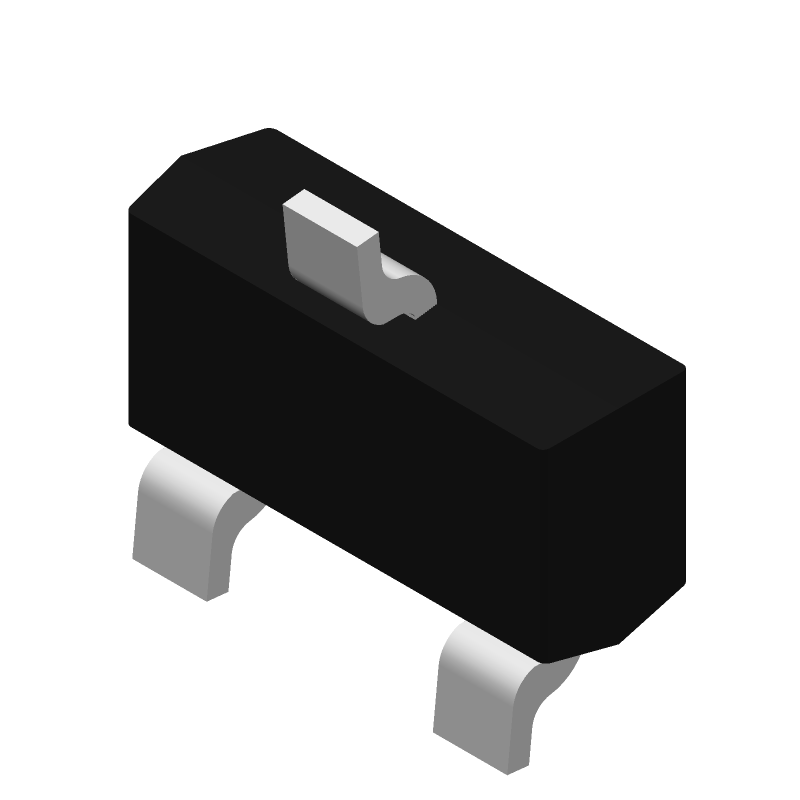 ZVP1320FTA datasheet
by Diodes Incorporated
ZVP1320FTA datasheet
by Diodes Incorporated