A good PCB layout for the TN1215-600B should prioritize thermal dissipation. Place the device near a thermal pad or a heat sink, and ensure good copper pour connectivity to dissipate heat efficiently. Avoid routing critical signals near the device to minimize electromagnetic interference.
To ensure reliable operation across the full temperature range (-40°C to 150°C), follow the recommended operating conditions, and consider the device's thermal derating. Implement proper thermal management, and ensure the device is soldered correctly to prevent thermal resistance.
For EMI and EMC compliance, ensure proper PCB layout, use shielding, and implement filtering on input/output lines. Follow STMicroelectronics' application notes and guidelines for EMI and EMC compliance. Additionally, consider using a common-mode choke and a ferrite bead to reduce electromagnetic radiation.
To troubleshoot and debug issues with the TN1215-600B, use a systematic approach. Verify the device's pinout, check for proper soldering, and ensure correct voltage supply. Use oscilloscopes and logic analyzers to monitor signals, and consult STMicroelectronics' application notes and technical support resources.
The TN1215-600B's power-on reset (POR) ensures the device resets correctly during power-up. Consider the POR timing and voltage thresholds in your system design. Ensure that the power supply is stable and meets the device's voltage requirements to prevent unwanted resets or malfunctions.
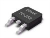 TN1215-600B datasheet
by STMicroelectronics
TN1215-600B datasheet
by STMicroelectronics
 Findchips
 Findchips