A 4-layer PCB with a solid ground plane and thermal vias is recommended. Ensure a minimum of 1mm clearance around the device for airflow and heat dissipation.
Implement a thermal management system, such as a heat sink or fan, to maintain a junction temperature below 125°C. Also, ensure proper PCB design and component selection to minimize thermal resistance.
Use X7R or X5R ceramic capacitors with a minimum capacitance of 10uF for input and output filtering. Ensure the capacitors are placed close to the device and have a low ESL (Equivalent Series Inductance).
Use a shielded enclosure, keep sensitive components away from the device, and ensure proper PCB layout and grounding. Implement EMI filters or common-mode chokes on input and output lines if necessary.
Apply the input voltage (VIN) first, followed by the enable signal (EN). Ensure the input voltage is stable before applying the enable signal.
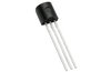 STX13003G-AP datasheet
by STMicroelectronics
STX13003G-AP datasheet
by STMicroelectronics