A good PCB layout for optimal thermal performance involves placing the device near a thermal pad or a heat sink, and ensuring good thermal conductivity between the device and the PCB. A 2-layer or 4-layer PCB with a solid ground plane is recommended. Avoid placing thermal vias under the device, and ensure that the PCB is designed to minimize thermal resistance.
To ensure reliable operation at high temperatures, ensure that the device is operated within the recommended temperature range (up to 150°C for the STPS24045TV). Use a suitable thermal interface material (TIM) between the device and the heat sink, and ensure good airflow around the device. Monitor the device's junction temperature and adjust the thermal design accordingly.
The recommended soldering conditions for the STPS24045TV are: peak temperature of 260°C, soldering time of 10-30 seconds, and a maximum of 2 reflows. Use a soldering iron with a temperature range of 200-240°C, and ensure that the device is not exposed to temperatures above 260°C for more than 10 seconds.
The STPS24045TV requires a specific power sequencing to ensure proper operation. Ensure that the input voltage (VIN) is applied before the enable signal (EN), and that the output voltage (VOUT) is stable before applying the load. Use a power sequencing controller or a dedicated power management IC to ensure proper power sequencing.
The recommended input capacitor for the STPS24045TV is a 10-22μF ceramic capacitor with a voltage rating of 10-16V. The recommended output capacitor is a 10-22μF ceramic capacitor with a voltage rating of 5-10V. Use X5R or X7R dielectric capacitors for optimal performance.
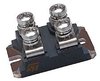 STPS24045TV datasheet
by STMicroelectronics
STPS24045TV datasheet
by STMicroelectronics