A 2-layer or 4-layer PCB with a solid ground plane and thermal vias is recommended. Ensure a minimum of 1mm clearance around the device for airflow and heat dissipation.
Implement a thermal management system, such as a heat sink or fan, to keep the junction temperature below 150°C. Also, ensure proper PCB design and layout to minimize thermal resistance.
Use X7R or X5R ceramic capacitors with a voltage rating of 10V or higher. For input capacitors, use 10uF to 22uF, and for output capacitors, use 10uF to 47uF. Ensure the capacitors are placed close to the device pins.
Use a shielded enclosure, and ensure the PCB is designed with EMI mitigation in mind. Use a common-mode choke or ferrite bead on the input and output lines, and consider adding EMI filters or shielding to the device.
Apply the input voltage (VIN) first, followed by the enable signal (EN). Ensure the input voltage is stable before applying the enable signal. A soft-start circuit can be used to reduce inrush current.
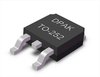 STD95N2LH5 datasheet
by STMicroelectronics
STD95N2LH5 datasheet
by STMicroelectronics
 Findchips
 Findchips