The STD5N60M2 is a power MOSFET, and as such, it does not have a specific maximum operating frequency. However, it is suitable for high-frequency switching applications up to several hundred kHz.
To minimize switching losses, ensure that the gate drive voltage is sufficient (typically 10-15V) and that the gate resistance is minimized. A gate driver IC can be used to provide a high-current, low-impedance drive signal.
The SOA of the STD5N60M2 is not explicitly stated in the datasheet, but it can be estimated based on the device's thermal and electrical characteristics. As a general rule, the device should not be operated at a voltage greater than 80% of the maximum rated voltage (600V) and a current greater than 80% of the maximum rated current (5A) simultaneously.
To protect the STD5N60M2 from overvoltage and overcurrent conditions, consider using a voltage clamp or a transient voltage suppressor (TVS) to limit voltage spikes, and a current sense resistor or a current limiter to detect and respond to overcurrent conditions.
The thermal resistance of the STD5N60M2 is typically around 2.5°C/W (junction-to-case) and 60°C/W (junction-to-ambient). This means that the device's junction temperature will increase by 2.5°C for every watt of power dissipation. Proper thermal management, such as using a heat sink, is essential to ensure the device operates within its safe operating area.
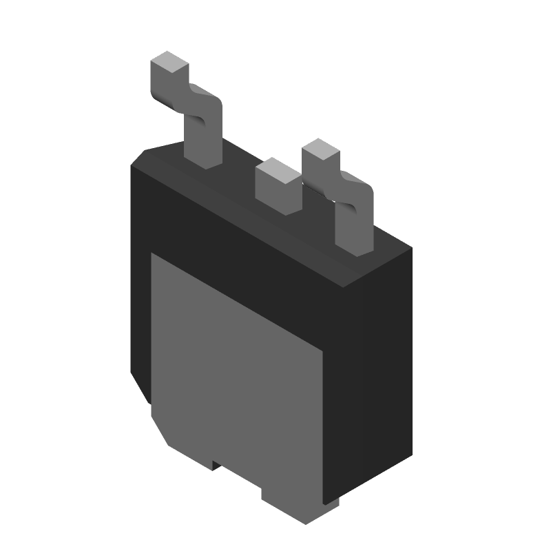 STD5N60M2 datasheet
by STMicroelectronics
STD5N60M2 datasheet
by STMicroelectronics
 Findchips
