The recommended PCB footprint for the S3JB-13-F is a standard SOT23 package with a 1.5mm x 1.5mm pad size, with a 0.5mm keep-out area around the package.
To ensure proper biasing, connect the input pin (VIN) to a stable voltage source, and decouple the input with a 1uF capacitor to ground. Also, ensure the output pin (VOUT) is properly decoupled with a 10uF capacitor to ground.
The S3JB-13-F can handle a maximum input voltage of 18V, but it's recommended to operate within the specified input voltage range of 2.5V to 15V for optimal performance and reliability.
The S3JB-13-F is rated for operation up to 125°C, but it's recommended to derate the output current and input voltage as the temperature increases to ensure reliable operation.
The output voltage of the S3JB-13-F can be calculated using the formula: VOUT = (R1 / R2) * (VIN - VREF), where R1 and R2 are the resistors in the feedback network, VIN is the input voltage, and VREF is the internal reference voltage (typically 1.25V).
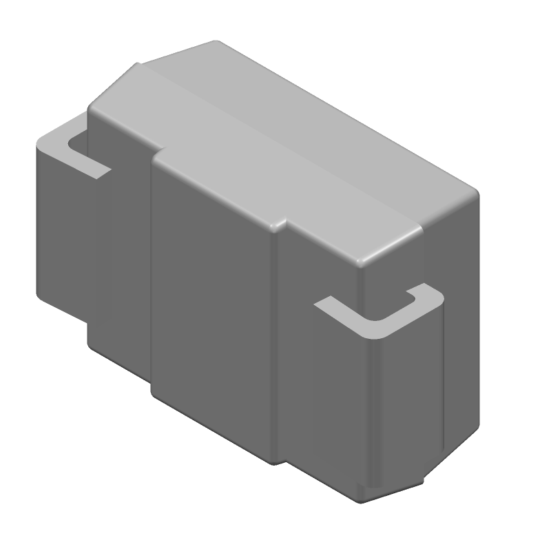 S3JB-13-F datasheet
by Diodes Incorporated
S3JB-13-F datasheet
by Diodes Incorporated