A good PCB layout for the LF33CDT involves keeping the input and output capacitors close to the device, using a solid ground plane, and minimizing the length of the input and output traces. Additionally, it's recommended to use a star-ground configuration and to avoid routing high-frequency signals near the device.
To ensure stability, make sure to follow the recommended capacitor values and PCB layout guidelines. Additionally, ensure that the input and output capacitors are of high quality and have low ESR. It's also important to decouple the input and output pins with capacitors to prevent oscillation.
The LF33CDT can handle input voltages up to 30V, but it's recommended to operate within the specified input voltage range of 3.5V to 15V for optimal performance and reliability.
The LF33CDT is rated for operation up to 125°C, but its performance may degrade at high temperatures. It's recommended to derate the device's performance and ensure proper thermal management to prevent overheating.
The output voltage of the LF33CDT can be calculated using the formula: Vout = (Vin x R2) / (R1 + R2), where Vin is the input voltage, R1 and R2 are the feedback resistors, and Vout is the output voltage.
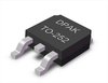 LF33CDT datasheet
by STMicroelectronics
LF33CDT datasheet
by STMicroelectronics