TE Connectivity provides a recommended PCB layout and land pattern in their application note AN-104, which can be found on their website. It's essential to follow these guidelines to ensure proper soldering and to prevent thermal issues.
When selecting an FSM103 variant, consider factors such as the required current rating, voltage rating, and operating temperature range. Refer to the datasheet and TE Connectivity's selection guide to determine the most suitable part number for your specific application.
The FSM103 has a maximum junction temperature of 150°C. To ensure proper heat dissipation, use a heat sink or thermal pad, and follow the recommended PCB layout and land pattern. Additionally, consider the thermal resistance of the device and the ambient temperature of the operating environment.
Yes, the FSM103 is designed for high-reliability applications and meets various industry standards, such as AEC-Q101 for automotive and IATF 16949 for quality management. However, it's essential to consult with TE Connectivity's technical support and review the device's certification and compliance documents to ensure it meets the specific requirements of your application.
To troubleshoot issues with FSM103, start by reviewing the datasheet and application notes. Check for proper PCB layout, soldering, and thermal management. Use diagnostic tools, such as thermal imaging or oscilloscopes, to identify the root cause of the issue. If the problem persists, consult with TE Connectivity's technical support for further assistance.
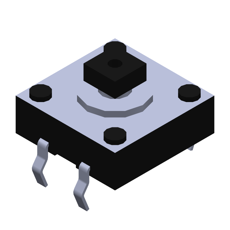 FSM103 datasheet
by TE Connectivity
FSM103 datasheet
by TE Connectivity