A good PCB layout for the DSS5540X-13 involves keeping the input and output traces short and separate, using a solid ground plane, and placing decoupling capacitors close to the device. A 4-layer PCB with a dedicated power plane and a solid ground plane is recommended.
To ensure proper biasing, connect the EN pin to a voltage source (e.g., VCC) through a 10kΩ resistor, and connect the FB pin to the output voltage through a resistive divider. The resistive divider should be chosen to set the output voltage to the desired value.
The DSS5540X-13 has a thermal shutdown feature that turns off the device when the junction temperature exceeds 150°C. To ensure reliable operation, ensure good airflow, use a heat sink if necessary, and avoid operating the device near its maximum power rating for extended periods.
Choose an inductor with a high saturation current rating, low DC resistance, and a suitable inductance value (e.g., 1-10 μH). The inductor should be able to handle the peak current and have a low core loss to minimize energy loss.
To minimize EMI, use a shielded inductor, keep the layout compact, and use a common-mode choke or ferrite bead on the input and output lines. Additionally, ensure good grounding and use a metal can or shielded enclosure for the device.
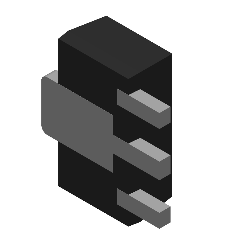 DSS5540X-13 datasheet
by Diodes Incorporated
DSS5540X-13 datasheet
by Diodes Incorporated