A good PCB layout for the DDZ12CQ-7 should minimize lead inductance, ensure good heat dissipation, and keep the device away from high-frequency noise sources. A recommended layout is to use a ground plane, keep the input and output traces short and wide, and use a thermal relief pattern for the device's thermal pad.
To ensure proper biasing, follow the recommended operating conditions in the datasheet. Typically, this means applying a voltage source to the anode (pin 1) and cathode (pin 2) with a suitable resistor to limit the current. The recommended bias voltage is 12V, and the recommended bias current is 5mA.
The maximum allowable power dissipation for the DDZ12CQ-7 is 500mW. Exceeding this limit can cause the device to overheat, leading to reduced performance, reliability issues, or even failure.
While the DDZ12CQ-7 is primarily designed for voltage regulation, it can be used in switching regulator applications. However, it's essential to ensure the device is properly biased and the switching frequency is within the recommended range (typically up to 100kHz). Additionally, consider the device's power dissipation and thermal management in your design.
To protect the DDZ12CQ-7 from EOS and ESD, follow proper handling and storage procedures. Use anti-static wrist straps, mats, and packaging materials. In the circuit design, consider adding transient voltage suppressors (TVS) or zener diodes to clamp voltage transients, and use resistors to limit current surges.
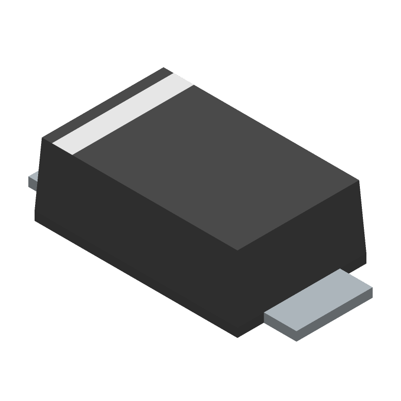 DDZ12CQ-7 datasheet
by Diodes Incorporated
DDZ12CQ-7 datasheet
by Diodes Incorporated
 Findchips
