Texas Instruments recommends a 4-layer PCB with a solid ground plane, and to keep the clock signal traces short and away from other signals. Additionally, use a common mode choke or ferrite bead to filter the clock signal.
Use a low-ESR capacitor (e.g. 0.1uF) as close as possible to the VCC pin, and a 10uF capacitor in parallel to filter out noise. Ensure the power supply can provide a clean and stable voltage, and consider using a voltage regulator if necessary.
The CDCVF2510APW can handle clock frequencies up to 250 MHz, but the actual frequency limit may depend on the specific application and PCB layout. It's recommended to consult the datasheet and perform simulations to ensure the device can meet the required frequency.
The CDCVF2510APW can be configured using the SEL0-SEL2 pins to select the desired clock frequency and output format. Consult the datasheet for the specific pin configurations and settings required for the desired application.
The typical power consumption of the CDCVF2510APW is around 30-40mA, but this can vary depending on the clock frequency, output format, and other factors. Consult the datasheet for more detailed power consumption information.
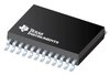 CDCVF2510APW datasheet
by Texas Instruments
CDCVF2510APW datasheet
by Texas Instruments
 Findchips
 Findchips