The maximum safe operating area (SOA) for the 2N5432 is not explicitly stated in the datasheet, but it can be estimated based on the device's thermal and electrical characteristics. As a general rule, it's recommended to operate the device within the boundaries of the maximum ratings and ensure that the device does not exceed the maximum junction temperature (Tj) of 150°C.
To ensure the 2N5432 is properly biased for linear operation, you should ensure that the base-emitter voltage (Vbe) is within the recommended range of 0.6-0.8V, and the collector-emitter voltage (Vce) is within the recommended range of 1-10V. Additionally, the base current (Ib) should be limited to prevent saturation, and the collector current (Ic) should be within the recommended range of 0-5A.
The recommended PCB layout for the 2N5432 involves keeping the leads as short as possible, using a solid copper plane for the collector pin, and ensuring good thermal conductivity between the device and the heat sink. Thermal management is critical, and it's recommended to use a heat sink with a thermal resistance of less than 10°C/W to keep the junction temperature (Tj) below 150°C.
Yes, the 2N5432 can be used as a switch, but it's essential to ensure that the device is properly biased and that the switching frequency is within the recommended range. The device should be operated in the saturation region (Vce < 0.5V) to minimize power losses, and the base current should be sufficient to ensure fast switching times. Additionally, the device's thermal characteristics should be considered to prevent overheating.
To protect the 2N5432 from electrostatic discharge (ESD), it's recommended to handle the device with anti-static precautions, such as using an anti-static wrist strap or mat. The device should be stored in an anti-static package, and the PCB should be designed with ESD protection in mind, such as using ESD protection diodes or resistors.
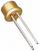 2N5432 datasheet
by Vishay Siliconix
2N5432 datasheet
by Vishay Siliconix